Materials Mechanics
Monocular 3D Video Extensometer



Monocular 2D Optical Strain Measurement System
Monocular 3D Optical Strain Measurement System
High-Speed Monocular 3D Optical Strain Measurement System
Stereo 3D Optical Strain Measurement System
Optical Strain Measurement System – Educational Edition
2D Optical Microscopic Strain Measurement System


Strain Measurement of Parallel Lap Welds
Residual Deformation Measurement of Drilled Welded Plates
Full-Field Strain Measurement of Weldments in Compression
Tensile Deformation Measurement of 0.3mm Fiber Filament
Unmarked Compression Deformation Measurement of Composite Materials

Deformation Measurement of Artificial Cardiac Patch
Keycap Vibration Measurement: Quantifying Press and Rebound Dynamics
Headband Deformation Measurement: Analyzing Bending Position and Unloading Recovery
High-Temperature DIC Measurement of Wafer Thermal Warpage: Quantifying Warpage vs. Temperature
UAV Dynamic Tracking Measurement: Capturing Flight Trajectory and Attitude Changes

 0755-86347753

Published: 2026-07-21
When people first encounter DIC digital image correlation technology, a question arises:
Does DIC Use a Camera to Film Material Deformation and Then Analyze It with Software?
On the surface, DIC indeed uses a camera to capture the specimen deformation process, but it is not simply filming a video. Ordinary video mainly records what happened during the test, while DIC needs to answer further:
▪ Where does the material start to deform?
▪ How much deformation occurred at each location?
▪ Where does strain concentration appear?
▪ How does deformation develop with load and time?
▪ Which areas may suffer damage or failure first?
The core value of DIC is to convert image changes on the specimen surface into quantifiable displacement, strain, 3D topography and data curves through image matching and computation.
DIC, short for Digital Image Correlation, usually translated as digital image correlation method or digital image correlation technology, is a non-contact optical measurement method based on image analysis.
In mechanical tests of materials and structural testing, DIC can use cameras to record specimen surface images before and after loading, compute surface displacement through correlation matching algorithms, and further obtain the strain distribution.
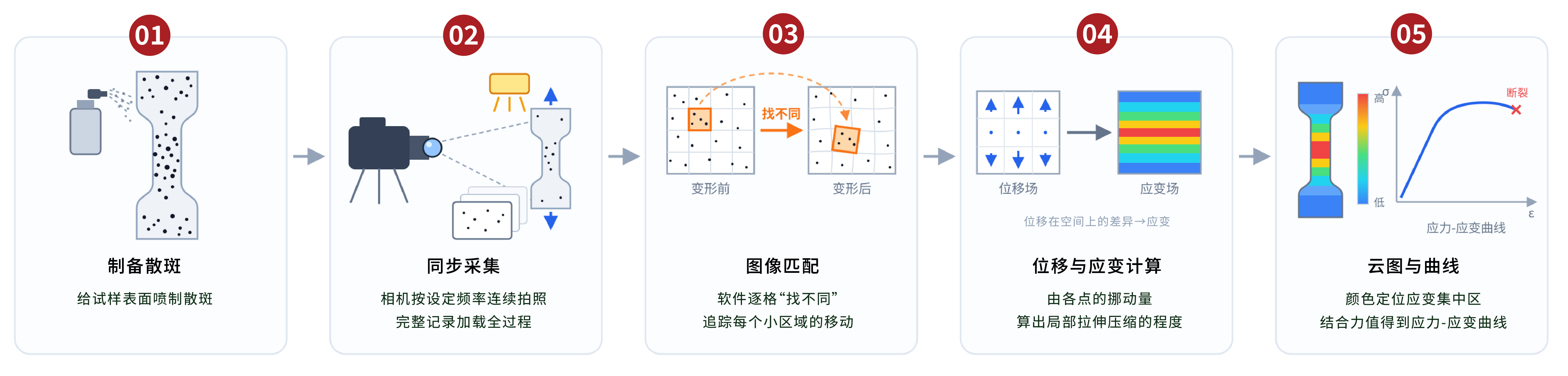
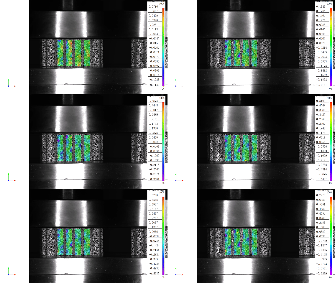
Unlike methods that can only measure a single position or one gauge length, DIC can acquire relatively dense displacement and strain data within the camera-visible measurement area, presenting the material's deformation process as contour maps, curves and more.
Simply put:The camera is responsible for capturing images, and the DIC algorithm for computing displacement and strain from them.
The basic process of DIC can be summarized as: first create recognizable image features on the specimen surface, then track the position changes of these features during deformation.
1. Apply speckle on the specimen surface
Before testing, randomly distributed black-and-white speckles usually need to be applied to the specimen surface.
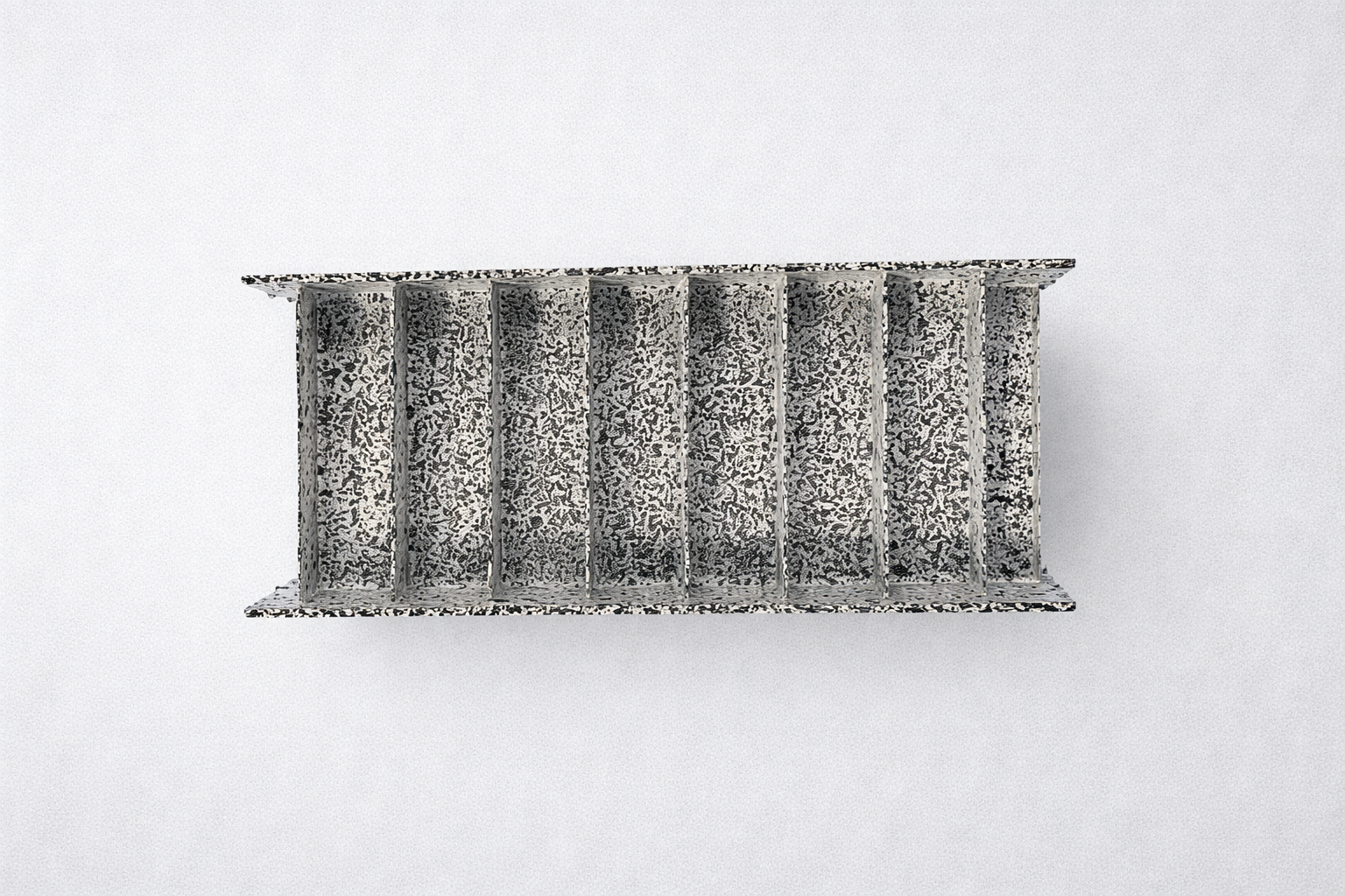
Speckle can be understood as the visual fingerprint of the specimen surface. Every small area has different grayscale and texture features, by which the software can recognize and track that area.
The size, density, randomness and contrast of the speckle all affect subsequent image matching and measurement results.
2. Continuously capture deformation images
After the test starts, the camera continuously captures images at the set sampling frequency.
The software usually uses the image before loading or at a specified moment as the reference image, and compares subsequent images as deformed images.
3. Track the Movement of Image Areas
DIC software divides the measurement area into many small areas, also called subsets.
Then the algorithm searches subsequent images for the image features most similar to the reference image, determining where these areas moved and what shape changes occurred.
This process is like high-precision spot-the-difference: what is compared is not visible changes, but subtle changes in image grayscale and texture features.
4. Compute strain from displacement
When the software obtains the movement direction and distance of each area, a displacement field can be formed.
By comparing displacement changes between adjacent positions, the strain field can be further computed to analyze the degree to which the material is locally stretched, compressed or sheared.
Therefore, strain is not directly captured by the camera, but further solved from the displacement results and the strain calculation method.
Analysis parameters such as subset size, step size, strain window and filtering method may also affect the final results.
What DIC yields is not just a test video; it can also output various kinds of data usable for material analysis and engineering verification, including:
▪ Displacement in X and Y directions
▪ 3D spatial displacement
▪ Axial strain and transverse strain
▪ Shear strain
▪ Principal strain
▪ Displacement contour maps
▪ Strain contour maps
▪ Time-displacement curves
▪ Time-strain curves
▪ Stress-strain curves
▪ 3D topography and point cloud data
Among them, displacement and strain contour maps use different colors to represent magnitudes, helping engineers intuitively identify areas of large deformation, strain concentration and potential weak positions.
Not necessarily.
Camera resolution affects spatial sampling capability, but DIC measurement accuracy is not determined by pixel count alone.
The measurement results of a DIC system are also affected by the following factors:
▪ Speckle size and speckle quality
▪ Lens resolution and lens distortion
▪ Camera noise and dynamic range
▪ Light source stability
▪ Specimen surface reflections and shadows
▪ Camera installation stability
▪ Camera synchronization accuracy
▪ Calibration accuracy
▪ Measurement field of view
▪ Image sampling frequency
▪ DIC algorithm and analysis parameters
▪ Environmental vibration and air disturbance
For example, even with a high-pixel camera, if the speckle is too large, too small, insufficient in contrast or unevenly distributed, the software may still struggle to recognize image features stably.
Similarly, lighting changes, local reflections, camera vibration and calibration deviations may also be recognized by the algorithm as specimen deformation, affecting displacement and strain results.
Therefore, DIC is not simply a high-pixel camera plus analysis software, but a complete measurement chain composed of speckle, camera, lens, light source, optical path, calibration, synchronization, algorithms and data analysis.
DIC is usually divided into 2D DIC and 3D DIC. The main difference between the two is whether out-of-plane motion of the specimen toward the camera can be measured.
Which Tests Suit Single-Camera 2D DIC?
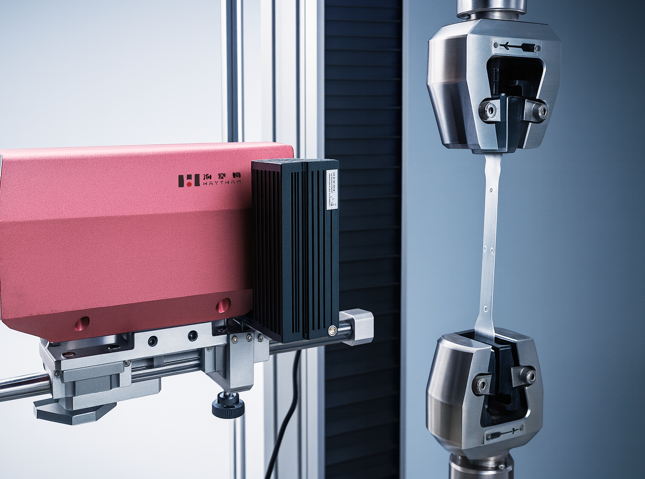
Single-camera 2D DICusually suits the following scenarios better:
▪ The specimen surface is approximately flat
▪ Deformation occurs mainly in-plane
▪ The distance between specimen and camera stays basically unchanged
▪ No obvious warping or rotation in the measurement area
2D DIC mainly calculates displacement from changes within the image plane.
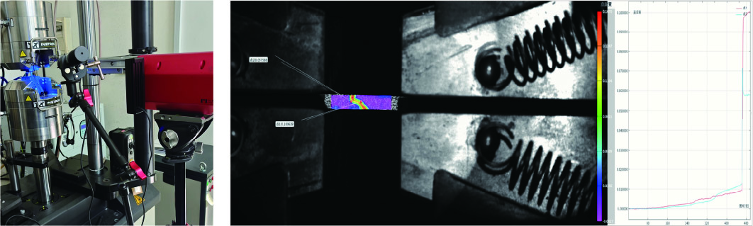
If the specimen moves toward or away from the camera during testing (out-of-plane motion), its size and position in the image change accordingly. The software may mistake this in-and-out motion for in-plane deformation of the specimen surface, causing measurement error.
How Does Stereo 3D DIC Measure Spatial Deformation?
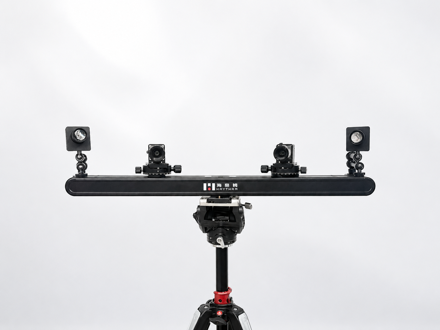
Stereo 3D DICUsually two cameras are used to observe the specimen simultaneously from different viewpoints.
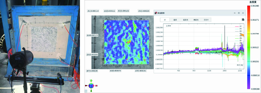
Its principle is like human eyes: through the difference between two viewpoints, it reconstructs the 3D spatial coordinates of the specimen surface and measures displacement in the X, Y and Z directions.
Stereo 3D DIC better suits:
▪ Curved specimens
▪ Bending and warping tests
▪ Tests with obvious out-of-plane motion
▪ 3D deformation measurement of complex structures
▪ 3D topography and 3D strain analysis
Haytham Technologysingle-camera 3D DICThrough a dedicated optical path, image information from different viewpoints is merged into one camera; combined with spatial calibration and 3D computation methods, it reconstructs the 3D topography, displacement and strain of the specimen surface.
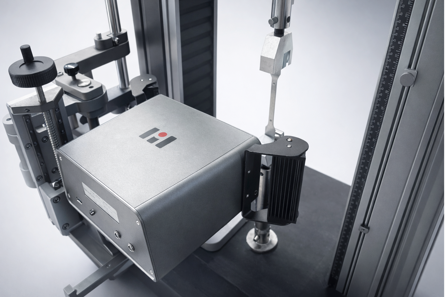
This approach does not directly infer depth from ordinary single-camera images; it obtains multiple effective viewpoints within one camera and lens architecture to complete 3D measurement.
Compared with multi-camera setups, single-camera 3D DIC reduces the complexity of synchronization, installation and commissioning between cameras, suitable for high-speed testing, limited installation space and application scenarios with high equipment integration requirements.
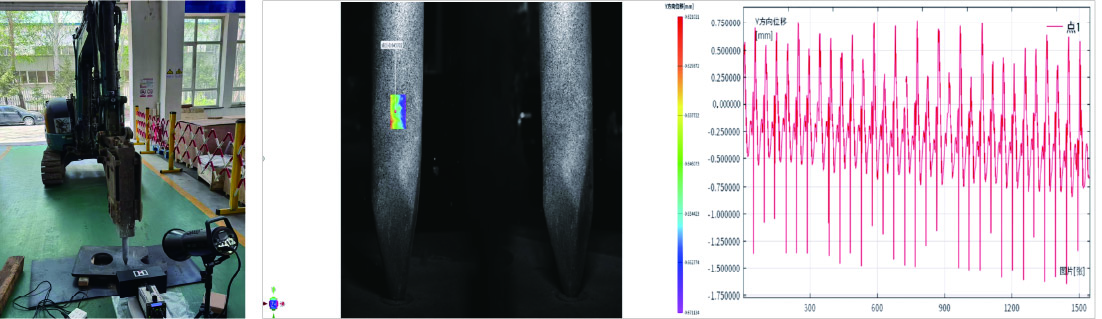
Mechanical tests of materials usually yield results such as strength, stiffness, yield and fracture, but in research and failure analysis, engineers often also need to know the specific location where deformation occurs and its development process.
For example:
▪ Where does damage start first?
▪ Is the material deformation uniform?
▪ In which area is the strain concentrated?
▪ How does the strain near the crack evolve?
▪ How do different structural areas deform in coordination?
▪ Where do simulation results deviate from measured results?
▪ Did local anomalies already appear before specimen failure?
Relying only on a single measuring point or the average over one gauge length can hardly describe these spatial differences completely.
DIC can acquire displacement and strain distributions over the entire measurement area, extending material testing from single-point data or averages to full-field deformation analysis.
DIC uses non-contact optical measurement; the camera and lens need not be mounted directly on the measured area.
Therefore, when testing lightweight, flexible, thin-walled, tiny orlarge deformation specimens, the influence of sensor mass, adhesive layers and lead wires on specimen stiffness, mass and motion state can be reduced.
Common DIC application objects include:
▪ Films and rubber
▪ Composite materials
▪ Foam and porous materials
▪ Fibers and filaments
▪ Flexible electronic devices
▪ Lightweight parts
▪ Tiny specimens
▪ Large-deformation specimens
▪ Curved surfaces and complex structures
For specimens with obvious local deformation or large deformation ranges, DIC can also observe differences between areas through full-field contour maps.
When image quality, sampling frequency and data storage meet requirements, DIC tests can still be re-analyzed based on the original images after the test ends.
Engineers can, according to subsequent research needs:
▪ Re-select the measurement area
▪ Adjust analysis parameters
▪ Set gauge length arbitrarily
▪ Extract displacement data at different positions
▪ Extract strain data of different areas
▪ Re-observe the local deformation process
▪ Compare strain distributions at different stages
This means that the same set of test images can be used for data extraction from different positions, ranges and analysis objectives.
DIC mainly measures displacement and strain; it does not directly measure force.
After the DIC system is synchronized with the testing machine or force sensor, the force values recorded during the test can be correlated with the strain data measured by DIC.
Combined with the specimen's original cross-sectional dimensions, nominal stress can be computed and a stress-strain curve formed.
If true stress, true strain or complex cross-section analysis is needed, calculations must follow the specific test method, specimen shape and data processing requirements.
Yes.
DIC provides a relatively dense displacement and strain field within the measurement area, and is therefore often used for validating finite element simulation models.
Engineers can compare measured displacement and strain distributions with finite element results and analyze:
▪ Whether the deformation trends are consistent
▪ Whether strain concentration positions correspond
▪ Whether the boundary conditions are reasonably set
▪ Whether the material parameters are accurate
▪ Whether the contact relationships match reality
▪ Whether local structures need optimization
Compared with comparing only single measuring points, comparison based on full-field data provides more spatial information, supporting material parameter identification, model updating and structural design optimization.
By configuring different cameras, lenses, light sources, acquisition frequencies and environmental accessories, DIC can be applied to many material and structure testing scenarios, including:
▪ Tensile testing
▪ Compression testing
▪ Bending testing
▪ Shear testing
▪ Fatigue testing
▪ Vibration testing
▪ Impact testing
▪ High-speed dynamic testing
▪ High-temperature mechanical tests
▪ Low-temperature mechanical tests
▪ Large-deformation measurement
▪ Micro-scale measurement
▪ Crack propagation analysis
▪ Composite material testing
▪ Finite element simulation validation
Different test scenarios have different requirements for measurement field of view, spatial resolution, sampling frequency, temperature adaptability and synchronization; configurations should be selected according to specimen size, deformation speed and test purpose.
Both DIC and ordinary video can use cameras to record the test process, but their purposes and outputs differ.
Ordinary video is mainly for observation and recording, answering what happened during the test.
DIC, in contrast, converts images into displacement and strain data through speckle recognition, image matching, spatial calibration and strain computation, answering:
▪ Where does the deformation occur?
▪ How much deformation occurred at different positions?
▪ When does the deformation start?
▪ How does strain concentration develop?
▪ What may cause the damage and failure?
Therefore, DIC does not simply film material deformation; it quantitatively analyzes the material deformation process through a complete optical measurement and image computation chain.
▪ Does DIC require speckle application?
Most DIC tests require surface image features with randomness and contrast, so black-and-white speckle patterns usually need to be applied. If the measured surface itself has a stable, random and clear natural texture, it may also be used directly for image correlation analysis, but the image quality should be verified in advance.
▪ Can DIC measure displacement as well as strain?
Yes. DIC first computes displacement through image matching, then computes strain from the displacement changes between different positions.
▪ Is DIC a non-contact measurement method?
Yes. DIC captures specimen surface images through a camera; the measurement equipment does not need to directly touch the measured area.
▪ 2D DICCan Bent Specimens Be Measured?
If obvious out-of-plane motion or surface curvature changes exist during bending, 2D DIC may produce additional errors. Such tests are usually better suited to DIC solutions capable of measuring 3D spatial motion.
▪ What does DIC measurement accuracy mainly depend on?
DIC measurement accuracy is related to many factors such as camera, lens, field of view, speckle, lighting, calibration, system stability, environmental conditions, algorithms and analysis parameters; it cannot be judged by camera pixels alone.
▪ Can DIC be used for high-speed impact testing?
Yes, but the sampling frequency, exposure time, light source brightness and high-speed camera configuration must be selected according to the deformation speed, ensuring the key deformation process is clearly recorded.
Filming a material test video is not difficult; what has real measurement value is converting images into reliable, analyzable and verifiable data.
Haytham Technology continues research around DIC vision sensing, optical measurement and image algorithms, building a complete measurement chain covering image acquisition, spatial calibration, displacement solving, strain analysis and result output.
With DIC, engineers can learn not only whether the specimen finally fractures, but also where deformation starts, how it propagates, which areas show strain concentration first, and why local damage eventually develops into overall failure.
This is exactly the core value that distinguishes DIC digital image correlation technology from ordinary video recording.





 Downloads

